Electromagnetic induction
After studying this section you should be able to:
- calculate the flux linkage through a coil of wire in a magnetic field
- explain how electromagnetic induction occurs due to changes in flux linkage
- apply Faraday’s law and Lenz’s law
This section covers the following topics
- Flux and Flux Linkage
- Faraday's Law
- What Direction?
- The Transformer
Flux and flux linkage
Almost everything we do, apart from sleeping in the dark, relies on electromagnetic induction. Induction is used to generate electricity in power stations and to transform its voltage as it passes through the distribution system.
The effects of induction are explained by using the concept of flux. Although the existence of flux has long been discredited, an awareness of its meaning is useful to understand the laws of induction as set out by Faraday and Lenz.
Flux provides a useful model for explaining the effects of magnetic fields.
Like gravitational and electric fields, magnetic fields act at a distance. Magnetic field patterns are used to show the forces that are exerted around a magnet or electric current. These forces are exerted without any physical link between the magnet or current that causes the field and a magnetic material or current placed within the field. In the days of Faraday and Lenz, they were attributed to the effects of flux.
The current view is that these forces can be attributed to ‘exchange particles’.
When drawing magnetic field patterns:
- the relative strength at different points in the field is shown by the separation of the field lines
- the closer the lines are together, the stronger the field
- these field lines represent magnetic flux, which is imagined as occupying the space around a magnet and being responsible for the effect of a magnet field.
To integrate the flux model with today’s explanation of magnetic effects in terms of magnetic field strength, this can be thought of in terms of a flux density, being represented by the concentration of magnetic field lines. Flux density is the flux per unit area so flux is now defined in terms of the magnetic field strength and the area that the field permeates.
KEY POINT - The magnetic flux, Φ, through an area, A, is defined as the product of the magnetic field strength and the area normal to the field.
Φ = B × A
Magnetic flux is measured in webers (Wb) where 1 Wb is the flux through an area of 1 m2 normal to a uniform field of strength 1 T.
This definition relates the equivalence of the modern concept of magnetic field strength to that of the older ‘flux density’ concept.
The diagram shows the flux through a rectangular coil in a uniform magnetic field.
Image
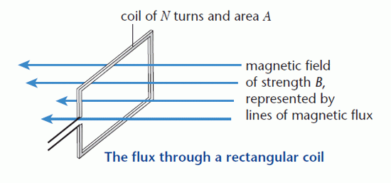
When the coil is rotated, it ‘cuts’ through the flux, or field lines and an e.m.f. is induced.
The size, or magnitude, of the induced e.m.f. depends on:
- the amount of flux through the coil
- the speed of rotation
- the number of turns on the coil.
Each turn on the coil has a flux linkage which changes as the coil rotates. The flux linkage of a coil of N turns is NΦ, where Φ is the flux through the coil.
Movement of the coil parallel to the field does not induce an e.m.f., since no field lines are being ‘cut’. The induced e.m.f. has its greatest value when the movement of the coil is perpendicular to the field.
Faraday’s law
Electromagnetic induction occurs whenever the magnetic field through a conductor changes. This can be due to a conductor moving through a magnetic field or a conductor being in a fixed position within a changing magnetic field, such as that due to an alternating current. Both of these result in an e.m.f. being induced in the conductor.
Examples of electromagnetic induction include:
- moving a magnet inside a wire coil
- generating the high voltage necessary to ionise the vapour in a fluorescent tube and cause the spark needed to ignite the explosive mixture in a petrol engine
- changing the voltage of an alternating current, using a transformer.
In a power station, electricity is generated by an electromagnet spinning inside copper coils.
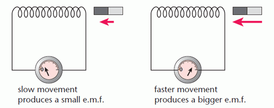
The diagram below shows the difference in the size of the e.m.f. when a magnet is moved at different speeds in a coil.
Image
Faraday’s law relates the size of the induced e.m.f. to the change in flux linkage.
KEY POINT - Faraday’s law states that: the size of the induced e.m.f. is proportional to the rate of change of flux linkage. As the proportionality constant is equal to 1, for a uniform rate of change of flux linkage this can be written as:
magnitude of induced e.m.f. N = ΔΦ / Δt where ΔΦ is the change of flux in time Δt.
To generate the high voltage needed to cause a spark, the flux has to change rapidly. This happens when the current in an electromagnet is switched off.
What direction?
Faraday’s law can be used to work out the size of an induced e.m.f. such as that across the wingtips of an aircraft flying in the Earth’s magnetic field. In Britain the Earth’s field makes an angle of 20° with the vertical, see the following diagram.
Image
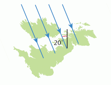
Unlike that of a bar magnet, the Earth’s magnetic field is from South to North. It can be considered to have two components, vertical and horizontal.
An aircraft flying in a North–South direction is cutting across the vertical component only, while flying East–West involves cutting across the horizontal component in addition.
The induced e.m.f. arises as a consequence of the force on the free electrons in the metal of the aircraft frame. As the aircraft travels through the air, the movement of these electrons forms a current in the opposite direction to that of flight. Fleming’s left hand rule can be used to work out the direction of the force on the electrons and hence the direction of the induced e.m.f.
All the charged particles experience a force due to their movement through a magnetic field, but the force is too weak to affect anything other than the free electrons.
In the case of an aircraft flying from North to South:
- the current is South–North
- the magnetic field being ‘cut’ is vertically downwards
- the force on the free electrons is towards the East.
This results in a charge imbalance and a voltage across the wingtips. The direction of the e.m.f. induced in the aircraft and when a magnet moves into a coil of wire can be worked out using Lenz’s law.
KEY POINT - Lenz’s law states that: the direction of an induced e.m.f. is always in opposition to the change that causes it.
If the induced e.m.f. in the aircraft caused electrons to flow from West to East, it would produce a force in a Northerly direction – opposite to the motion of the aircraft. This does not happen because there is no complete circuit.
The diagram below shows that when the North pole of a magnet is moved into one end of a coil, the induced e.m.f. causes an induced current in an anticlockwise direction. When current passes in a coil, the magnetic field is similar to that of a bar magnet, the North pole being the end where the current passes anticlockwise.
Image
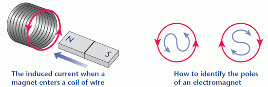
The direction of the induced current is reversed by reversing the magnet or its direction of movement.
If the induced current was in the opposite direction, it would attract the magnet into the coil and generate electricity with no energy input.
Lenz’s law is a re-statement of the principle of conservation of energy; the induced current opposes the motion of the magnet so work has to be done to move the magnet against the induced magnetic field. This work is the energy transfer to the circuit needed to cause a current.
Combining Faraday’s and Lenz’s laws gives the equation for induced e.m.f.:
KEY POINT -
Image
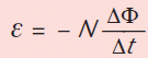
Where ε is the induced e.m.f. The negative sign shows that the induced e.m.f. is in opposition to the change of flux causing it.
The transformer
Transformers use changing magnetic fields to change the size of an alternating voltage. An alternating current passing in one coil (the primary) induces an e.m.f. in an adjacent coil (the secondary).
The diagram below shows the flux when the two coils are wound on an iron core.
Image
The e.m.f. is induced whether or not there is a secondary circuit. If there is a complete circuit, there is also an induced current.
In a transformer:
- alternating current in the primary produces an alternating magnetic field
- this is reinforced by the high-permeability iron core
- the flux concentrates in the iron
- an e.m.f. is induced in the secondary because of the changing flux linkage.
Iron is easily magnetised; its magnetic domains contribute to the strength of the magnetic field.
It follows from the last bullet point that the induced e.m.f. is proportional to the number of turns on the secondary coil.
KEY POINT - The relationship between the voltages and numbers of turns for an ideal transformer is:
Image
A transformer constructed from lowresistance coils on a laminated iron core is close to ideal.
This states that the voltages are in the same ratio as the numbers of turns. In an ideal transformer there is no energy loss in the wires or the core so the power output from the secondary is equal to the power input to the primary and the currents are in the inverse ratio to the voltages.
PROGRESS CHECK
Image
Category